8
LT1248
ripple fed back to the error amplifier is minimized. Note
that switching ripple on the high impedance lines could get
into the multiplier from the I
AC
pin and cause instability.
The LT1248 provides an internal 25k resistor in series with
the low impedance multiplier current input so that only a
capacitor from the I
AC
pin to GND is needed to filter out the
noise. The maximum multiplier output current, which
limits the system line current, is set by the R
SET
according
to the formula: I
M(MAX)
= 3.75V/R
SET
.
Oscillator Frequency and Maximum Line
Current Settling
Oscillator frequency is set by R
SET
and C
SET
. Ramp ampli-
tude is 5V and C
SET
charging current is set by V
REF
/R
SET
.
Typical discharging time for C
SET
= 1nF is 250ns. R
SET
should always be determined first to set the maximum
multiplier output current for system line current limit. For
a 300W preregulator, with R
SET
= 15k, I
M(MAX)
= 3.75V/15k
= 250礎. With a 4k resistor R
REF
from M
OUT
to the 0.2&
line current sense resistor R
S
, the line current limit is: (I
M
" 4k)/R
S
. As a general rule, R
S
is chosen according to:
R
S
= I
M(MAX)
" R
REF
" V
LINE(MIN)
K(1.414)P
OUT(MAX)
where P
OUT(MAX)
is the maximum power output and K is
usually between 1.1 and 1.3 depending on efficiency and
resistor tolerance. With R
SET
selected, C
SET
can then be
determined by: C
SET
= 1.5/(Frequency " R
SET
). For 100kHz,
C
SET
= 1.5/(100kHz " 15k) = 1nF. For optional double
protection, the LT1248 provides a current limit compara-
tor. When the comparator trips at 0V, the GTDR pin quickly
goes low to shut off the MOS switch. A resistor divider
from V
REF
to R
S
(Figure 2) senses the voltage across the
line current sense resistor and the current limit is set by:
I
LINE
= [(7.5V/R1) + 50礎](R2/R
S
), where 50礎 is I
PKLIM
.
S
A
PPLICATI
U
U
I FOR ATIO
With I
LINE
and R
S
chosen, let R1 = 10k, then R2 =
(I
LINE
" R
S
)/0.8mA.
Always use R
SET
to set the primary line current limit. The
PK
LIM
comparator is only for secondary protection. The
secondary limit should be higher than the primary limit;
6.5A is good (5A for primary limit) for a 300W regulator.
When line current reaches the primary limit, V
OUT
drops to
keep the line current constant, and system stability is still
maintained by the current loop which is controlled by the
current amplifier. When line current reaches the second-
ary limit, the comparator controls the system and loop
hysteresis may occur and can cause audible noise.
Synchronization
The LT1248 can be synchronized to a frequency that is up
to 1.6 times the natural frequency. With a 200ns one-shot
timer on-chip, the LT1248 provides flexibility on the
synchronizing pulse width. Because the EN/SYNC pin also
serves the chip shutdown function, the pulses at the pin
should not go below 3V and must go below 5V with widths
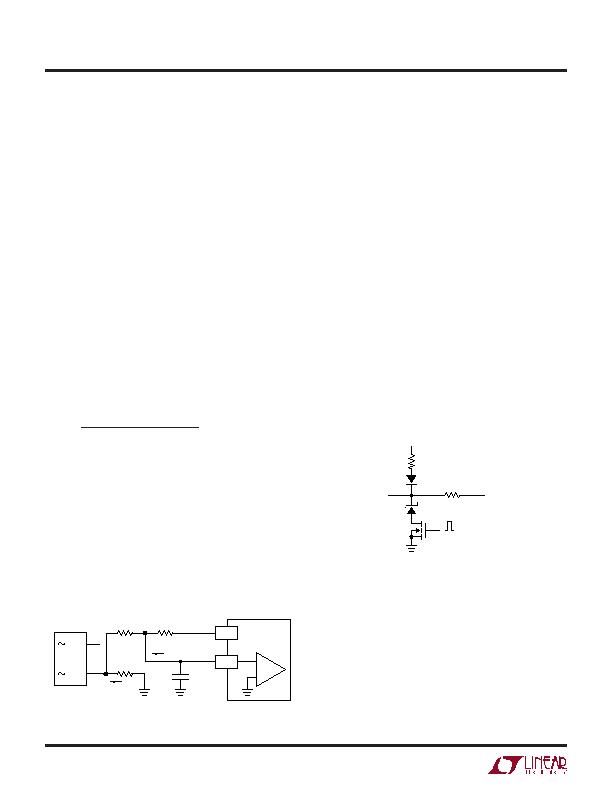
greater than 200ns. The Figure 3 circuit will synchronize
the LT1248.
Figure 2
+
I
LINE
R
S
0.2&
I
PKLIM
C1
1nF
7.5V
V
REF
PK
LIM
C1 IS TO REJECT NOISE, CURRENT
LIMIT DELAY IS ABOUT 2祍.
R2
1.6k
R1
10k
+
1248 F02
Overvoltage Protection
Because of the slow loop response necessary for power
factor correction, output overshoot can occur with sudden
load removal or reduction. To protect the power compo-
nents and output load, the LT1248 provides an overvolt-
age comparator which senses the output voltage and
quickly shuts off the current switch. In Figure 4, because
there is no DC current going through R3, R1 and R2 set the
regulator output DC level: V
OUT
= V
REF
[(R1 + R2)/R2], with
R1 = 1M, R2 = 20k, V
OUT
is 382V.
Figure 3
30k
V
REF
200k
V
CC
1N4148
1N4685
3.6V
EN/SYNC
VN2222
SYNC PULSE
AT LEAST 200ns
1248 F03
发布紧急采购,3分钟左右您将得到回复。
相关PDF资料
LT1249IS8#PBF
IC PFC CTRLR AVERAGE CURR 8SOIC
LT1577CS-3.3/2.8#TRPBF
IC REG CTRLR DUAL OUT 16SOIC
LT1640HIN8#PBF
IC CONTRLR HOTSWAP NEGVOLT 8-DIP
LT1641IS8#TR
IC CTRLR HOTSWAP POS VOLT 8SOIC
LT1939IDD#TRPBF
IC REG DL BUCK/LINEAR 12DFN
LT3092MPST#TRPBF
IC PROG CURRENT SOURCE SOT223-3
LT3150CGN#TRPBF
IC REG CTRLR SGL POS ADJ 16-SSOP
LT3500HMSE#TRPBF
IC REG DL BUCK/LINEAR 16-MSOP
相关代理商/技术参数
LT1248IS#PBF
制造商:Linear Technology 功能描述:IC PFC CURRENT 25V SOIC-16 制造商:Linear Technology 功能描述:IC, PFC, CURRENT, 25V, SOIC-16
LT1248IS#TR
功能描述:IC PFC CTRLR AVERAGE CURR 16SOIC RoHS:否 类别:集成电路 (IC) >> PMIC - PFC(功率因数修正) 系列:- 产品培训模块:GreenChip Synchronous Rectification Control Family of ICs 标准包装:1 系列:- 模式:间歇导电(DCM) 频率 - 开关:- 电流 - 启动:- 电源电压:8.6 V ~ 38 V 工作温度:-20°C ~ 150°C 安装类型:表面贴装 封装/外壳:14-SOIC(0.154",3.90mm 宽) 供应商设备封装:14-SO 包装:Digi-Reel® 其它名称:568-5348-6
LT1248IS#TRPBF
功能描述:IC PFC CTRLR AVERAGE CURR 16SOIC RoHS:是 类别:集成电路 (IC) >> PMIC - PFC(功率因数修正) 系列:- 产品培训模块:GreenChip Synchronous Rectification Control Family of ICs 标准包装:1 系列:- 模式:间歇导电(DCM) 频率 - 开关:- 电流 - 启动:- 电源电压:8.6 V ~ 38 V 工作温度:-20°C ~ 150°C 安装类型:表面贴装 封装/外壳:14-SOIC(0.154",3.90mm 宽) 供应商设备封装:14-SO 包装:Digi-Reel® 其它名称:568-5348-6
LT1249
制造商:LINER 制造商全称:Linear Technology 功能描述:Power Factor Controller
LT1249_01
制造商:LINER 制造商全称:Linear Technology 功能描述:Power Factor Controller
LT1249C
制造商:LINER 制造商全称:Linear Technology 功能描述:Power Factor Controller
LT1249CN8
功能描述:IC PFC CTRLR AVERAGE CURR 8DIP RoHS:否 类别:集成电路 (IC) >> PMIC - PFC(功率因数修正) 系列:- 产品培训模块:GreenChip Synchronous Rectification Control Family of ICs 标准包装:1 系列:- 模式:间歇导电(DCM) 频率 - 开关:- 电流 - 启动:- 电源电压:8.6 V ~ 38 V 工作温度:-20°C ~ 150°C 安装类型:表面贴装 封装/外壳:14-SOIC(0.154",3.90mm 宽) 供应商设备封装:14-SO 包装:Digi-Reel® 其它名称:568-5348-6
LT1249CN8#PBF
功能描述:IC PFC CTRLR AVERAGE CURR 8DIP RoHS:是 类别:集成电路 (IC) >> PMIC - PFC(功率因数修正) 系列:- 产品培训模块:GreenChip Synchronous Rectification Control Family of ICs 标准包装:1 系列:- 模式:间歇导电(DCM) 频率 - 开关:- 电流 - 启动:- 电源电压:8.6 V ~ 38 V 工作温度:-20°C ~ 150°C 安装类型:表面贴装 封装/外壳:14-SOIC(0.154",3.90mm 宽) 供应商设备封装:14-SO 包装:Digi-Reel® 其它名称:568-5348-6